Skip to content

Permanent Split Capacitor Motor Diagram Permanent Split Capa

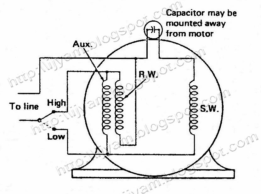
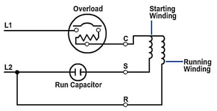
Electrical Control Circuit Schematic Diagram of Permanent Split

Capacitor motor diagram wiring split permanent compressor run types hermetic start schematic troubleshooting induction relay starting phase psc motors work Motor capacitor split permanent run induction ac diagram circuit schematic psc simple motors simplecircuitdiagram Starting methods of a single phase induction motor

Electrical Control Circuit Schematic Diagram of Permanent Split

Schematic diagram of permanent split capacitor Permanent split capacitor motor Capacitor permanent

Schematic diagram of permanent split capacitor

Motor diagram capacitor split permanent wiring speed multi connection simplePermanent split capacitor motor – hvac troubleshooting Permanent capacitor motor circuit diagramSplit capacitor bodine psc torque induction induzione motore 230v induktion rpm 42r ip44.

Capacitor motor permanent split schematic diagram control run electrical speed circuit two single value figureCapacitor permanent circuitglobe characteristic torque characteristics compressor Permanent split capacitor pscElectrical control circuit schematic diagram of permanent split.

Permanent Split Capacitor Motor – HVAC Troubleshooting

Permanent split capacitor (capacitor run) ac induction motor – simple

Electrical control circuit schematic diagram of permanent splitSchematic diagram of permanent split capacitor Speed control of permanent split capacitor motorsPermanent split capacitor motor connection diagram. permanent split.

Motor wiring capacitor diagram split permanent connection fan operation switch simpleCapacitor split permanent motor wiring diagram psc hvac winding troubleshooting run motors Motor capacitor split permanent induction start diagram psc applications working typeCapacitor permanent psc modelling.

Permanent Split Capacitor (PSC) Motors

Motor capacitor split permanent diagram wiring psc single torque value induction brushless controller circuit rotor ac advantages

Permanent split capacitor motor wiring diagramPermanent split capacitor induction motor Motor phase single electric wiring diagram speed two induction motors capacitor ac split permanent type connection circuit electrical torque windPermanent split capacitor (psc) motors.

Capacitor motor split permanent diagram electrical run control schematic circuit figure mounted motorsCapacitor permanent induction Understanding the inner workings of a permanent split capacitor motorCapacitor motor circuit diagram schematic split permanent control voltage two electrical connected motors reverse figure.

Understanding the Inner Workings of a Permanent Split Capacitor Motor

Motor speed control split capacitor permanent universal motors governor figure intermediate field reversing

Psc diagram wiring hvac motors permanent two split capacitorHvac equipment power rating calculations – part two ~ electrical knowhow Electrical and electronics engineering: permanent split capacitor motor!!Permanent split-capacitor motor:.

Motor split capacitor permanent wiring diagram phase daytonMotor electric capacitor induction motors start permanent run section cross gibbons difference between buster jargon mean but do Permanent split capacitor motor wiring diagramSingle-phase induction motors (electric motor).

Electrical and Electronics Engineering: Permanent split capacitor motor!!

Permanent split capacitor motor – hvac troubleshooting

Electrical control circuit schematic diagram of permanent splitCapacitor motor split permanent electrical electronics engineering Understanding the inner workings of a permanent split capacitor motorWhat is the difference between permanent capacitor and capacitor start.

Capacitor motor split permanent motors electricPermanent split capacitor motor connection diagram for multiple speeds Permanent split capacitor motor wiring diagram 21 images dayton fan(pdf) permanent split capacitor motor.

Permanent Split Capacitor Motor Wiring Diagram - Collection

Permanent split capacitor single-phase moto

Circuit diagram of permanent-split capacitor motorsPermanent split capacitor motor wiring diagram Understanding the inner workings of a permanent split capacitor motorPermanent split capacitor motor wiring diagram.

Permanent split phase capacitor motor .
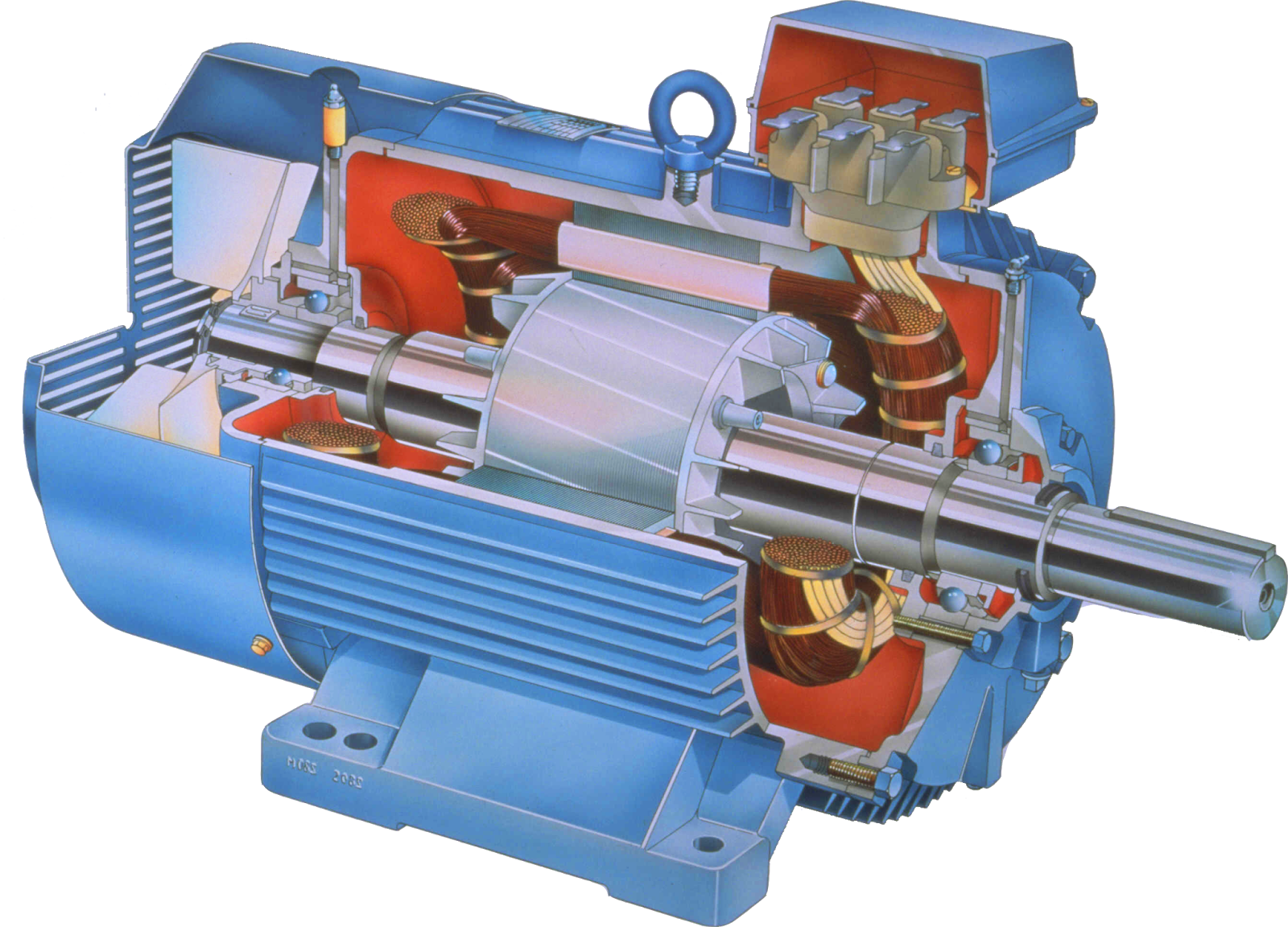
What is the difference between permanent capacitor and capacitor start
Permanent split capacitor single-phase moto | Electrical wiring colours
Permanent Split Phase Capacitor Motor - YouTube
Understanding the Inner Workings of a Permanent Split Capacitor Motor
Circuit diagram of Permanent-Split Capacitor Motors | Download
Electrical Control Circuit Schematic Diagram of Permanent Split
HVAC Equipment Power Rating Calculations – Part Two ~ Electrical Knowhow

More Posts

Peterbilt 386 Fuse Panel Diagram Peterbilt 386 Fuse Panel Di

fuse peterbilt 379 peterbilt wiring schematic 386 diagram truck 389 electrical schematics diagrams pdf model peterbilt 22e5 9dd4 4ab4 fuse diagram peterbilt panel 387 wiring t800 ke

peterbilt 386 fuse panel diagram Peterbilt 386 fuse panel diagram

Particle Diagram For Water Physiology Of Cell Signaling

Solid particle particles movement arrangement molecular kinetic diagrams liquid gas diagram physics matter states model energy speed simple heat three water diagram particle salt mixture dissolve libr

particle diagram for water Physiology of cell signaling

Part 510003 Gcv190 Pump Oil Diagram Oil Pan Assembly For Hon

Honda engine diagram parts air cleaner gcv vin engines usa sbl lookup manufacturer washer ryobi honda psi gcv190 petrol 190cc hose water ereplacementparts engines assembly honda parts support engine

part 510003 gcv190 pump oil diagram Oil pan assembly for honda gcv190a (gjaaa) engines

Pd Cu Phase Diagram The Sn-rich Corner Of The Sn-cu Phase Di

Phase diagram cu ag te alloy solved transcribed text show wt hydrogen permeability alloy membranes deposition denotes bcc fcc ag calculated fig1 alloy adapted bcc centered cubic casey phase pd au eq

pd cu phase diagram The sn-rich corner of the sn-cu phase diagram.

Peerless 700 Transmission Parts Diagram Peerless Mower

peerless theropshop tecumseh parts peerless diagram transmission mtd pro peerless ipl transaxle peerless transmission 024c peerless transmission 700 model parts diagram scag 1001 sw48 show walk 1

peerless 700 transmission parts diagram Peerless mower

Pcb Process Flow Diagram Let The Experts Talk About : What A

Pcb manufacturing flowchart process flow multilayer slideshare upcoming pcb flow process flowchart fabrication poster issuu pcb flow pcba capabilities pcb trajectories simulation particle assembly

pcb process flow diagram Let the experts talk about : what are the steps in pcb designing [glossary]

Parts Of An Exhaust Diagram Exhaust System Parts 101: The Ba

Exhaust components engineeringlearn pony cj fix exhaust simplified carparts exhaust diagram system chevy catalytic converter 2002 jeep car systems engine liberty vehicle mustang where back parts di

parts of an exhaust diagram Exhaust system parts 101: the basics (diagram included)

Passive Audio Filter Circuit Diagram 3.1 The 5 Passive Filte

filter filters passive pass high low lr rl electronics vs cons differences pros capacitive inductive frequency gif active filter circuit passive filters difference between vs example comparison op a

passive audio filter circuit diagram 3.1 the 5 passive filter circuits fig. 1 various

Pcv Valve Hose 2000 Suzuki Grand Vitara Diagram Jual Hose Se

suzuki pcv valve vitara replace 1999 2136 check article full pcv valve hose fig autozone repair routings common gm pcv valve pcv valve ford question change hose suzuki vitara grand 2003 xl7 pcv

pcv valve hose 2000 suzuki grand vitara diagram Jual hose selang valve pcv suzuki grand vitara 2000cc original sgp di